.png)


HDTV UNIVERSAL TEST CHART
- Introduction
- Product Software
HDTV UNIVERSAL TEST CHART
REFLECTANCE
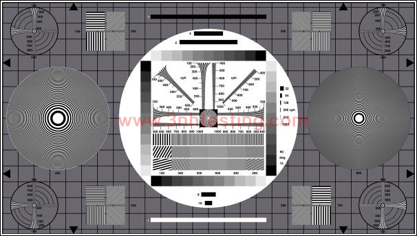
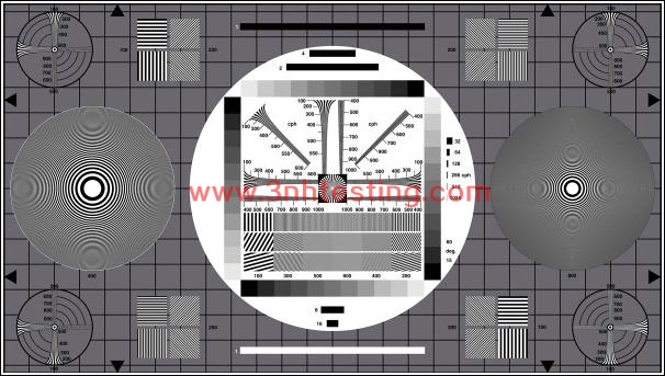
The TE167 test chart is designed for general appraisal of HDTV cameras.
The density of the four gray scales increases from D = 0.15 up to D = 1.65 (contrast = 40:1)
in gradations of D = 0.15. The surrounding gray area has a density of D ≈ 0.75. On this gray
area there is a 25/15 grid which corresponds to the grid of an electronic grid generator.
The test chart is used primarily for orientation assessment of the transmission characteristics
of an electronic camera. The circular figures and the grid allow an appraisal of the geometry.
The small sector star located in the center serves as a focusing aid.
The figures indicate the resolution - independent of the standard - in cph (cycles per picture
height). To read the resolution in “lines” simply double these values. The conversion in MHz
differs according to the standards (see table).
There are 16 fields with multi burst of 100 and 200 cph bars being inclined in angels to 45°
and 135° to the horizontal line.
Resolution can be determined visually in the upper part of the image center by means of
resolution wedges in 0°, 45° and 90° (up to 1000 cph = 2000 lines). Below the center three
rows of multi bursts of 100, 200, 300, 400, 500 and 600 cph are located with the fields of
higher frequencies close to the image center. The multi bursts of both bottom rows are
inclined in angels of 30° and 15° to the horizontal line. The three rows are mainly used
for electronic measurements, the bottom row in addition allows and approximate
measurement of vertical resolution.
The horizontal bars located above and below the gray scales impart information on the
transmission characteristics in medium frequency range (streaking).
Rough appraisal of half-tone reproduction is possible with the aid of the gray scale,
exact statements are, however, not possible due to the white surrounding area.
On the left and right sides two plates are located, the left one reaching a local
frequency of 400 cph and the right one of 800 cph. The zone plates serve to determine
the following characteristics of TV cameras and TV transmission systems:
A resolution in horizontal, vertical and diagonal direction
B resolution depending on the location of scanning
C effects of horizontal and vertical aperture corrections
D effects of interferences between the zone plate and television raster resp. the
shadow mask structure of colour picture tubes
E reaction during horizontal and vertical movements of the camera (or test chart):
dynamic resolution; temporary disturbances.
|
Standard |
1125 / 59.94 / 2:1 |
|
cph |
MHz |
|
100 |
6.9 |
|
200 |
13.7 |
|
300 |
20.6 |
|
400 |
27.4 |
|
500 |
34.3 |
|
600 |
41.2 |
|
700 |
48.0 |
|
800 |
54.9 |
|
900 |
61.7 |
|
1000 |
68.6 |
- Previous:GRID TEST CHART 16:9
Next:EBU / CAM TEST CHART
News
- 2017-07-08 How to use SFR resolution test char ...
- 2017-11-08 Attention before using T90-7 camera ...
- 2017-06-27 Definition and formation of pixel n ...
- 2014-06-12 Pantone TPX 2012 (175 New Colors)
- 2014-06-12 What is a colorimeter?
- 2014-06-12 Color Fastness
- 2014-06-12 Colorimeters Versus Spectrophotomet ...
- 2014-06-12 Integrating Sphere
